
 
|
Digital I/O Input Response Time
The response time of Visionscape to a change of an input signal is a combination of the hardware and software response times. The hardware response time for all inputs is within 200?s from voltage change on an external pin to go through the optical isolation and be received by the PC. Note that the optical isolation will invert the signals. For example, a high-to-low voltage transition will be seen by the software as a logical low-to-high transition.
The software response time varies by input pin and direction. Inputs 0-7 are tuned for a faster response on logical low-to-high transitions. Conversely, inputs 8-15 are tuned for faster response on logical high-to-low transitions. Trigger signals should be connected to pins in which the trigger direction matches the tuned response direction of the pin. The software response for logical low-to-high transitions on pins 0-7 (or high-to-low transitions on pins 8-15) is approximately 100?s. The software response time for the opposite transition of a logical high-to-low on pins 0-7 (or logical low-to-high on pins 8-15) is 10ms.
Cycles can be less than 10ms without missing trigger events. 10ms represents the longest delay for being notified of a transition. This is relevant for IO Display Windows as the minimum update speed of the visual indicators. It would also affect input triggers if they are set to use the opposite edge from the direction it is tuned. For example, when using pin 0 as a trigger on a logical high-to-low signal when that pin is tuned for a fast logical low-to-high response time. In this case the trigger may occur up to 10ms after the change of the signal state on the input pin.
The IO State datum of the Snapshot step reads the logical state of the input pins at the time of an image acquisition and is not subject to the 10ms response time limitation.
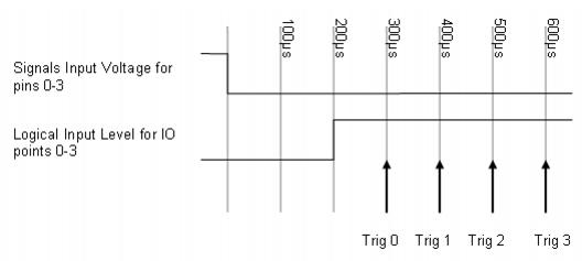
If multiple inputs change states simultaneously, the processing of those transitions is done sequentially. Therefore, the maximum response time to a trigger is subject to the number of asynchronous triggers that may occur simultaneously. The maximum response time to a trigger can be approximated by the number of possible simultaneous transitions x 100?s plus 200?s for the hardware response time. For example, if two inputs change state simultaneously, the two transitions would be processed within 400?s this is calculated by taking the 200?s hardware response for inputs + 200?s software response of the two changes at 100?s each.

The above diagram represents the scenario of 4 input triggers transitioning simultaneously. After the voltage goes from high to low on the pins 0-3, it can take up to 200?s for the computer to register the level of inputs 0-3 and be read as logic highs. Once the logical low-to-high transition has occurred, each trigger response can take 100?s to process. In the case of 4 simultaneous transitions, it can take up to 600?s for the last trigger response. If transitions occur simultaneously, the transitions will be processed in an indeterminate order.
 
|