

|
|
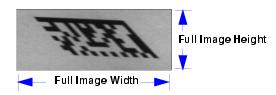
Skew Correction
The MS-4 Imager's CMOS image sensor has a "rolling shutter" mechanism that controls pixel integration row-by-row, unlike a global shutter, which performs light integration of all pixels at once. When a row of pixels has integrated light for the amount of time specified by the user-defined shutter speed, that row will be read out. The rows of the image are exposed individually in rapid sequence. As a symbol moves through the field of view, it is in a different position at each row read-out. This creates distortion, or "skew".
Note: The amount of blur in the image is an effect of shutter speed, and is not a factor in rolling shutter distortion.
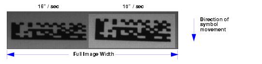
If the symbol enters the Imager's field of view from the top or bottom, distortion will occur on the y-axis. The image below shows two symbols entering the field of view from the top at different line speeds. As you can see, this causes the image to shrink along the y-axis. This is because the symbol is moving perpendicular to the CMOS sensor's row read-out. In other words, the bottom of the symbol is read out first, and as the symbol moves information is lost (the symbol enters pixel rows that have already been processed). This causes the symbol to appear to shrink vertically.
Note: If the symbol were to enter the field of view from the bottom, the captured image would be stretched along the y-axis.
The amount of rolling shutter distortion depends upon the amount of time it takes to read out an image row, and the line speed at which the target object is traveling. Therefore, one way to reduce skew is to speed up the read-out time per pixel row. This can be accomplished by reducing the column size of the image sensor.
For example, if the column size is reduced from 640 to 320, the time it takes to read out a row of pixels from the sensor is reduced by half, and image skew will be reduced by a factor of 2. As the column dimension of the image is reduced, the effect of rolling shutter distortion is reduced by the same factor.
Important: Reducing the row size of the image has no effect, because it does not change the row read-out time. Skew will remain the same regardless of row size.
Line Speed
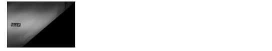
Distortion is corrected by shifting image rows in the direction opposite the symbol's movement on the line. The shift value of subsequent image rows is then increased. These shift values depend on the speed of the line. The faster the line speed, the greater the required shift values. More data loss is incurred at faster line speeds.
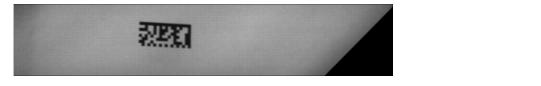
The image shown below was captured at a line speed of 40 inches per second, and it shows virtually no inherent skew. The black area of the image is unusable, since the information was lost as the symbol moved through the Imager's field of view.
The amount of data loss can be reduced by decreasing the image height or the row size of the image, which reduces the amount of travel represented during the image frame read-out. Note that the amount of distortion will not be changed, because the object will have traveled the same distance during the read-out of the target area.
|
|