

|
|
Ladder Logic
With our data types defined and tags created, we can now create the program using ladder logic. In this example, we will copy the user tag and match string from our controller tag to the Ethernet/IP output assembly on every cycle. Similarly, we will copy the results from the Ethernet/IP input assembly to our Results structure in the controller tags on every cycle.
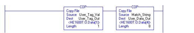
We will use the file copy function COP to copy data between our tags and the assemblies. Our first rung will copy the user tag from User_Tag_Val to the User_Tag_Out alias and the Match_String to the User_Data_Out alias. The Length parameter corresponds to the number of DINTs to copy, in the case of our 32 byte HE1600T_String type, the length will be 8. This will write the user tag and match string to the output assembly to be received by the VS-1 Smart Camera.
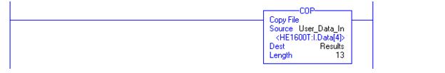
Next, we'll copy the results in the input assembly to our controller tag Results. Again, we use the COP function to copy the 52 byte Input_Assembly structure from the user data portion of the input assembly to the Results tag.
Finally, we'll create a trigger event using a timer. We will create a 1-second trigger by toggling an IO point every half second. To do this, we'll use the TON timer using our program tag name Trigger_Timer and set the Preset value to 500.
Then, on another rung, we will check for a timer done condition. If true, we then toggle the value of our Trigger and reset the timer.
On another rung, we will copy the value of a bit from the Trigger Value and write it to the IO bit 0 of the Ethernet/IP output. This will correspond to Virtual IO 129 in the Visionscape® program.

|
|