
 
|
Single Camera Pipeline Processing
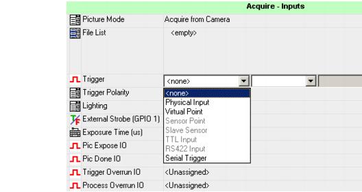
Pipeline execution occurs when processing of the previous image is overlapped with acquisition of the current image. The inspection must be triggered in order to enable single-camera pipeline. From FrontRunner™, select the Acquire Step in the Job Tree and enable the trigger by selecting the appropriate trigger source from Trigger, as shown in Figure 1-1.
FIGURE 1-1.

Selecting the Appropriate Trigger Source
In addition, set Trigger Polarity (High->Low or Low->High) based on the type of trigger signal used.
The types of triggers are:
- Physical Input - There are General Purpose I/O points available on GigE cameras. These can be configured as inputs, in which case they are valid triggers, or outputs, in which case they cannot be used as triggers. The definition of the points as inputs or outputs is done in the VisionSystemStep.
- Virtual Point - There are 2048 virtual I/O triggers. They are controlled through the AvpIOClient object and can be used in the same manner as physical inputs and output. However, Virtual I/O points are both inputs and outputs simultaneously. They can trigger internally the system from another Inspection. For more information, see "Triggering Acquisitions Internally" on page 1-13.
- Sensor Point - There are 4 built-in, dedicated sensor lines available. They are input only points.
- Slave Sensor - This is a special point used for master slave configurations.
- TTL Input - Unavailable on GigE or VS-1 Smart Camera systems.
- RS422 Input - Unavailable on GigE or VS-1 Smart Camera systems.
- Serial Trigger - This option triggers the acquisition when a user-specified string is received on either a TCP or RS-232 serial port. Select which port to listen on with the second drop down box and enter the match string in the edit box. The acquisition is triggered when the last character of the match string is received.
- IO Board DIO01 - Selects one of the general purpose inputs from a PCIe IO board. There are 16 input points and 16 output points. These points are also available as Virtual Points and will also appear in that list starting point number 160. There is no difference in operation whether the point is selected from the Virtual Point list or the IO Board list. NOTE: When selecting an IO Board input point for triggering, only the first 8 points can be used for low-to-high trigger events and only the second 8 input points can be used for high-to-low trigger events. If trigger events from both edges are required, the signal should be connected to two input pins, see the GigE Camera Guide for more information.
The timing of the trigger, the busy signal, and other related signals are shown in Figure 1-2, which shows a single-camera inspection running in pipeline mode, with overlapped processing and acquisition.
FIGURE 1-2.

Timing Diagram for Triggered Single Camera Inspection
The PicDone signal is asserted each time the image becomes available from the Digitizer. The image processing signal, Inspection Busy, occurs as soon as the image is digitized and is reset at the end of the cycle. At the end of the inspection, the Pass/Fail status is asserted and can be read while the data valid signal is active. The cycle starts again as soon as the data valid signal is turned Off, at which point the inspection releases the Snapshot's image. The next image acquisition occurs while the inspection is running on the previous one.
All signals can be programmed and attached to physical or virtual I/O outputs and are located as follows:
- Trigger, PicDone, ExposeDone: Acquire Step - The Expose signal is asserted whenever the camera sensor is ready to acquire a new image. This occurs before image readout from the camera is complete. The camera or part can be moved as soon as the Expose Signal has been asserted, allowing an application to overlap the changing of the scene with capture and processing of the previous scene.
- Busy, Data Valid: Inspection Step - The programmable data valid duration should be set according to the external system response time. When the Target Vision Accelerator is connected to a PLC, for example, the Data Valid duration should be programmed as the PLC scan rate in milliseconds. Both the high and low times of this signal are guaranteed to be at least the programmed pulse width.
 
|