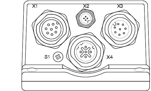
Rear Panel
Figure 2-2 details the
layout of the rear panel.
FIGURE 2-2.
Rear Panel Layout
- X1 - Power and Primary I/O (M12 A-coded, plug)
- X2 - External Light Power, Strobe only (M5, socket)
- X3 - Secondary I/O, Serial (M12 A-coded, socket)
- X4 - Industrial Ethernet (M12 D-Coded)
- S1 - QuicSet™ (Remove screw for access)
Note: On earlier productions units only. Function
not required.