

|
|
Output Opto Wiring
Figure 2-10 shows the output opto wiring for isolated input.
FIGURE 2-10.
.jpg)
GPIO Output Opto Wiring (NPN and PNP)
Note 1: GPIO IN COM typically connected to ground.
Note 2: GPIO IN COM typically connected to Voltage.Figure 2-11 shows the output opto wiring for isolated relay and PLC inputs.
FIGURE 2-11.
.jpg)
Output Opto Wiring (Relay and PLC Inputs)
Figure 2-12 shows the output opto wiring for non-isolated inputs.
FIGURE 2-12.
.jpg)
GPIO Output Opto Wiring (Relay and PLC Inputs)
Caution: The maximum current that can pass through the optoisolators is 50 mA. Non-isolation setup can cause damage to the VS-1 Smart Camera if excessive voltage is applied to the optoisolators.
FIGURE 2-13.
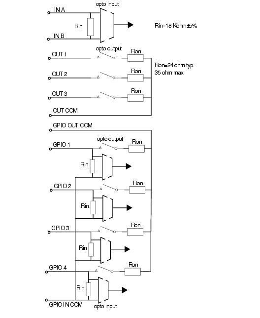
VS-1 Smart Camera I/O Simplified Circuit Diagram
|
|