

|
|
Configuring the Hardware
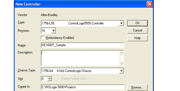
Within RSLogix 5000, use the File > New... menu to create a new project. Select the appropriate controller Type, Revision, Chassis Type, and Slot specific to your hardware configuration. Type in a name for your program in the "Name:" field, then click OK.
FIGURE F-21.
Once RSLogix 5000 creates the program, the Tree View displays different nodes for Tags, Tasks, etc. The last node in the tree is the "I/O Configuration". Right-click on this and select "New Module..." to add the Ethernet Bridge to the configuration.
FIGURE F-22.
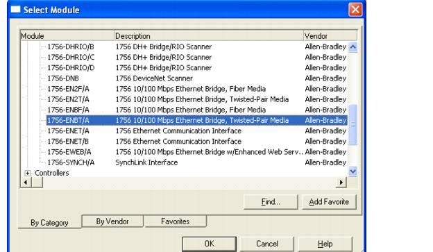
This is specific to your hardware setup; you need to know what bridge module is being used in your system. After clicking OK, you need to set up the IP configuration of the module.
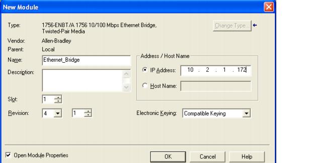
Set a useful name for the Ethernet Bridge in the "Name:" field and enter the static IP address of the bridge. In this example, the IP address is 10.2.1.172. In this configuration, the module is in slot 1 of the chassis. Click "OK" to continue.
FIGURE F-23.
Now, you can add a module for the VS-1 Smart Camera. Go back to the Tree and select the "Ethernet_Bridge" under the I/O Configuration, right-click it and select "New Module..." again. Then, you can select a "Generic Ethernet Module".
FIGURE F-24.
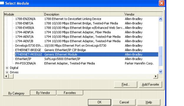
Click OK. The configuration dialog box for the generic module is displayed (Figure F-25).
FIGURE F-25.
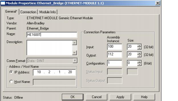
Enter "VS-1 Smart Camera" for the name. Enter the IP address of the camera. In this example, the static IP address of the camera is 10.2.1.20. For the I/O assemblies, the input assembly is instance 100, and it is 20 DINTs of data. The Output assembly is instance 112, and is also 20 DINTs of data. The "Configuration" assembly is not used by the camera, so enter in instance 1, size 0 and click OK.
At this point, the program creates a set of Controller Tags for each instance of the I/O assemblies of the new module. You can examine the tags by double-clicking "Controller Tags" in the RSLogix 5000 Tree View.
|
|