

|
|
Connecting the PLC Output Assembly Data to VS-1 Smart Camera Datums
Now we will insert a tool to read the match string data from the Ethernet/IP output assembly and connect it to the DMR tool. Clicking on the Data Matrix Tool in the Step Tree View, insert a Custom Step above the Data Matrix Tool. The Custom Step must be inserted above the Data Matrix tool so that it is executed and the Match String property is updated before the Data Matrix Tool runs.
Note: Custom Step is found under the Script tab of the Insert Step dialog.
FIGURE F-5.

Note: You can rename the step for better readability, if so desired (Figure F-6).
FIGURE F-6.

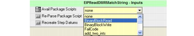
On the Custom Step property page, choose the BinaryBlockRead script from the Avail Package Scripts property (Figure F-7). This is a Perl script that takes data elements from an Ethernet/IP output assembly and connects them to Visionscape® datums in a vision job.
FIGURE F-7.
Several new properties will appear on the page (Figure F-8).
FIGURE F-8.
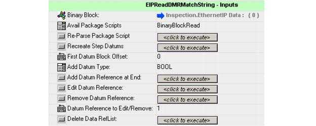
As previously defined, in this example there is a single string datum from bytes 0-31 of the user data portion of the output assembly. Since the string starts at byte 0, leave `First Datum Block Offset' set to the default value of 0.
Next, add the `Match String' data by changing `Add Datum Type' to String and clicking `Add Datum Reference at End'. Two new properties will appear on the property page, an input datum and a reference datum both named `0 Datum 1 (String)'.
FIGURE F-9.
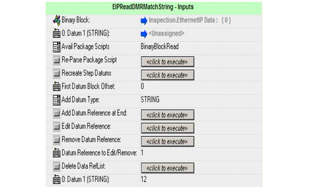
The 0 at the beginning of the name indicates a string starting at assembly byte location 0 of the user data block. The value 12 in the datum at the bottom of the property page indicates the default string length of 12 bytes. Since this example allows strings up to 28 bytes, change the last value to 28.
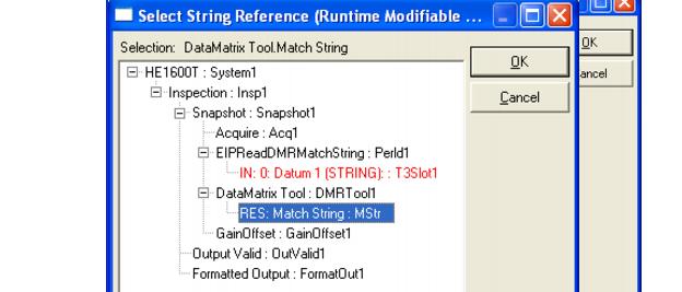
Next, select where to store the string in the vision job by selecting the input `0 Datum 1' reference selector and choosing the Match String of the Data Matrix Tool.
FIGURE F-10.
The property page should now show a single string datum starting at byte 0, of length 28 bytes that will be placed into the Data Matrix Tool Match String (Figure F-11).
FIGURE F-11.
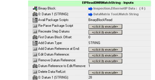
At this point, every time this inspection runs, the match string of the Data Matrix tool will be updated to reflect the string value in the Ethernet/IP output assembly at the time the inspection was triggered.
|
|