

|
|
Connecting VS-1 Smart Camera Results to the PLC Input Assembly Data
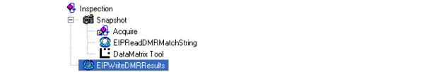
Next, we will insert a tool to take the results of the Data Matrix Tool and put them into the Input assembly that is sent back to the PLC from the VS-1 Smart Camera. To do this, insert another Custom Step into the job. Since we want to include results of the Data Matrix Tool, the Custom Step must be placed below the Data Matrix Tool so the results will be valid at the time the Custom Step executes. In this example, we will place it after the Snapshot step as follows:
FIGURE F-12.

We also rename this step also for readability.
FIGURE F-13.
Now, since we want to write data from Visionscape® to Ethernet/IP, choose the BinaryBlockWrite script from the Avail Package Scripts property. This Perl script will take the data from Visionscape® datums and place them into the Ethernet/IP input assembly's user data block.
FIGURE F-14.

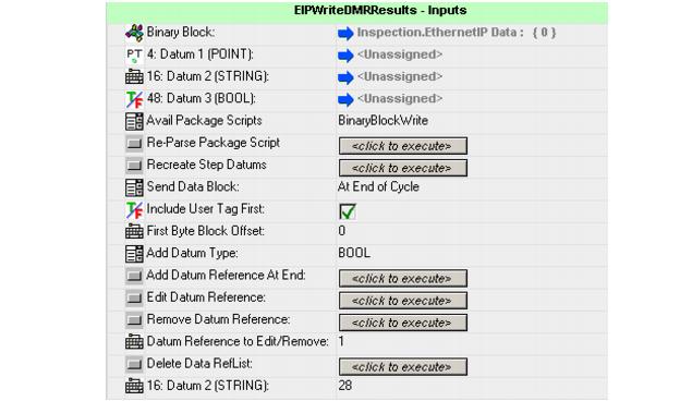
New properties will appear (Figure F-15):
FIGURE F-15.
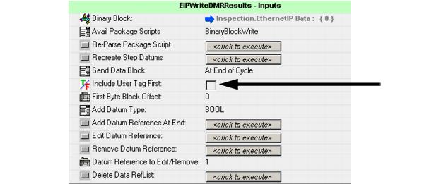
Since we want to echo the user tag back inside of the user data block in this example, select the box labeled Include User Tag First (Figure F-15).
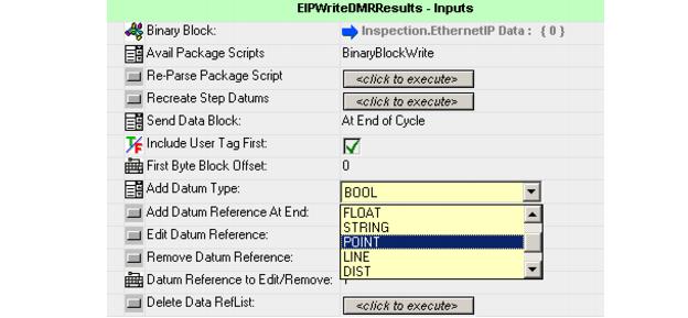
As defined earlier, the Ethernet/IP input assembly user data block will contain the Data Matrix center point, decoded DMR string and the DMR pass/fail status. Add those data types in sequence by first selecting Add Datum Type of Point and clicking `Add Datum Reference at End'.
FIGURE F-16.
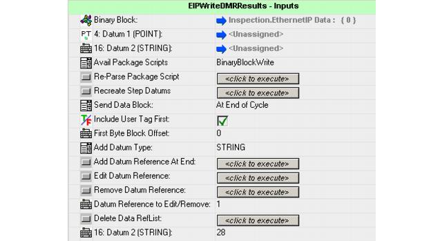
Then, choose Add Datum Type of String and click Add Datum Reference. Since we have allocated space for 28 characters in the data block, change the resource datum labeled Datum 2 (STRING) to 28 (Figure F-17).
FIGURE F-17.
Finally, add a Boolean reference by selecting Add Datum Type BOOL and clicking Add Datum Reference. The resulting property page should look like the one in Figure F-18. Showing a Point data type taking bytes 4-15, a String data type from bytes 16-47, followed by a Boolean data type in bytes 48-51. The first datum starts at byte 4 because we selected `Include User Tag First' which will place the user tag in bytes 0-3, ahead of the datum contents.
FIGURE F-18.
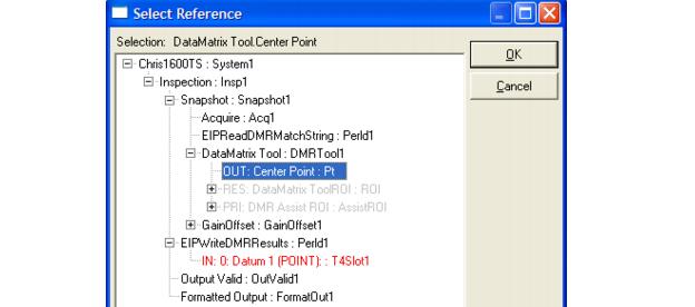
Next, connect each of the datums to the source of the result. In the case of the Point, connect it to the Data Matrix Tool Center Point (Figure F-19).
FIGURE F-19.
Similarly, connect the String to the Data Matrix Tool Text output and the Boolean to the Data Matrix Tool Status output. The resulting property page should look like the one in Figure F-20:
FIGURE F-20.
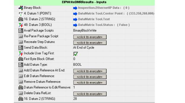
This step will now fill in the Ethernet/IP input assembly with the corresponding data at the end of each inspection cycle.
The Visionscape® job is now completed and ready to be downloaded to the camera.
|
|